Network segmentation through VLANs (Virtual Local Area Networks) is one of the most fundamental and effective security measures any UK business can implement. By dividing a single physical network into multiple isolated logical networks, VLANs prevent unauthorised devices from accessing sensitive resources, contain the blast radius of security incidents, and improve overall network performance.
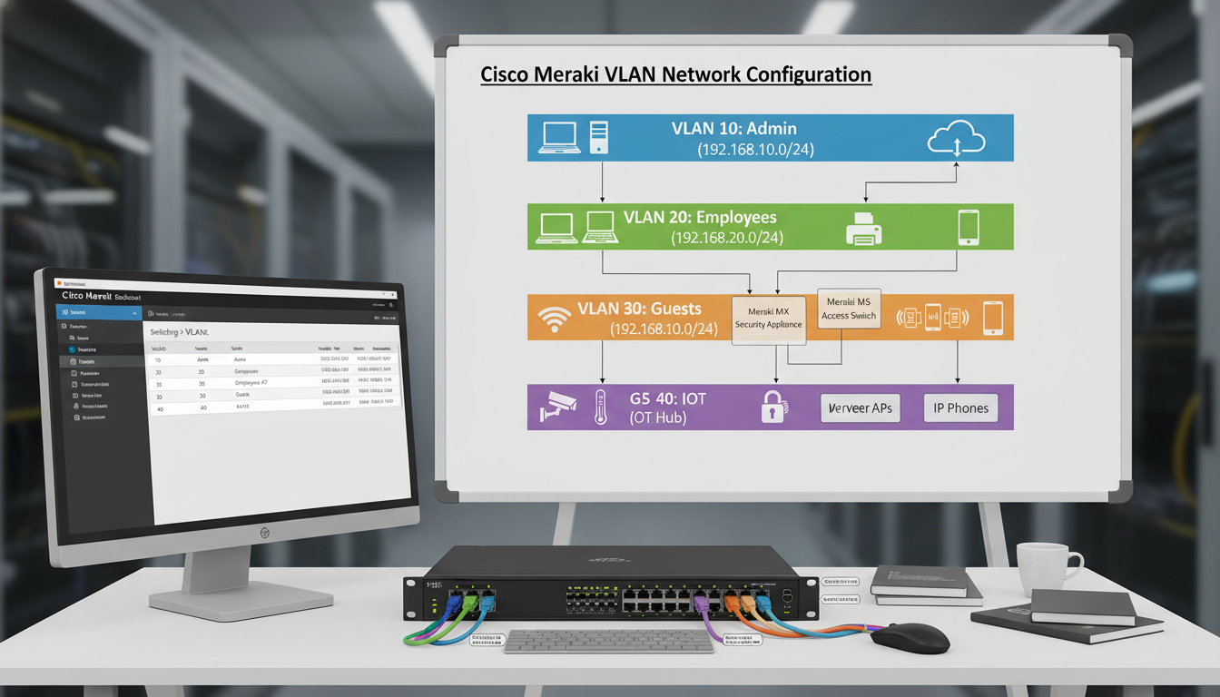
Cisco Meraki's cloud-managed networking platform makes VLAN configuration significantly more accessible than traditional CLI-based Cisco equipment. The Meraki dashboard provides a visual, intuitive interface for creating and managing VLANs, assigning ports, configuring DHCP, and setting up inter-VLAN routing — all without needing to memorise IOS commands or SSH into switches.
This guide walks through VLAN concepts, practical Meraki dashboard configuration, and common deployment patterns for UK businesses of all sizes. Whether you are segmenting a single office in Birmingham or deploying a consistent VLAN architecture across multiple sites in London, Manchester, and Edinburgh, the principles and configurations covered here will apply.
VLAN Concepts: Why Segmentation Matters
To understand why VLANs are essential, consider what happens without them. In a flat network — where every device shares the same subnet and broadcast domain — every device can potentially communicate with every other device. A receptionist's PC can reach the finance server. A guest's smartphone on the Wi-Fi can discover the domain controller. A compromised IoT device (a smart TV in a meeting room, for example) can scan the entire network and attack any vulnerable system it finds.
VLANs solve this by creating isolated network segments. Devices on VLAN 10 cannot communicate with devices on VLAN 20 unless you explicitly allow it through inter-VLAN routing rules. This means you can place your corporate PCs on one VLAN, your servers on another, your VoIP phones on a third, your guest Wi-Fi on a fourth, and your IoT devices on a fifth — each isolated from the others, with traffic between them controlled by firewall rules.
The UK Government's Cyber Essentials scheme does not explicitly require VLANs, but it does require network segmentation and access controls that prevent unauthorised access to systems and data. Implementing VLANs is the most practical way to meet these requirements for most businesses. Furthermore, the NCSC's network security guidance specifically recommends network segmentation as a key defensive measure, noting that “a flat network architecture provides an attacker with easy lateral movement once they gain initial access.” For businesses pursuing Cyber Essentials Plus certification, where an assessor actively tests your security controls, having proper VLAN segmentation demonstrates a mature security posture.
Planning Your VLAN Architecture
Before touching the Meraki dashboard, plan your VLAN architecture on paper. A well-designed VLAN scheme is logical, scalable, and documented. A poorly designed scheme creates management headaches and may actually impede rather than improve security.
For a typical UK SME with 30 to 100 employees, we recommend the following VLAN structure as a starting point. This can be adapted based on your specific requirements, but it covers the most common segmentation needs.
| VLAN ID | Name | Purpose | Subnet Example | DHCP Range |
|---|---|---|---|---|
| 1 | Management | Network device management (switches, APs, firewalls) | 10.0.1.0/24 | 10.0.1.100 – 10.0.1.200 |
| 10 | Corporate | Staff workstations and laptops | 10.0.10.0/24 | 10.0.10.50 – 10.0.10.250 |
| 20 | Servers | On-premises servers and infrastructure | 10.0.20.0/24 | Static assignments only |
| 30 | Voice | VoIP handsets and conference phones | 10.0.30.0/24 | 10.0.30.50 – 10.0.30.250 |
| 40 | Guest | Guest Wi-Fi — internet only, no internal access | 10.0.40.0/24 | 10.0.40.50 – 10.0.40.250 |
| 50 | IoT | Printers, smart displays, CCTV, building systems | 10.0.50.0/24 | 10.0.50.50 – 10.0.50.200 |
Configuring VLANs in the Meraki Dashboard
Meraki's cloud-managed approach means all VLAN configuration is done through the web-based dashboard at dashboard.meraki.com. There are no CLI commands to learn, no configuration files to manage, and changes take effect across your entire network within minutes.
To create VLANs on a Meraki MX security appliance (which handles inter-VLAN routing and DHCP), navigate to Security & SD-WAN > Addressing & VLANs. If VLANs are not already enabled, click “Enable VLANs” to switch from single-subnet mode to VLAN mode. Then click “Add VLAN” for each segment you planned above.
For each VLAN, configure the following settings: the VLAN ID (matching your plan), the VLAN name (descriptive and consistent), the subnet (the IP range for this VLAN), the MX appliance IP (the gateway address for devices on this VLAN, typically the .1 address), and the DHCP settings (whether the MX provides DHCP for this VLAN, the address range, lease time, and DNS servers).
Trunk Ports and Access Ports
Understanding the difference between trunk ports and access ports is essential for correct VLAN configuration on your Meraki switches.
An access port belongs to a single VLAN and connects to an end device like a PC, printer, or phone. Traffic on an access port is untagged — the connected device does not need to know about VLANs. The switch handles the VLAN assignment transparently. Most ports on your switches will be access ports.
A trunk port carries traffic for multiple VLANs simultaneously, using 802.1Q tags to identify which VLAN each frame belongs to. Trunk ports connect switches to other switches, switches to the MX appliance, and switches to wireless access points. They are the motorways of your VLAN infrastructure, carrying tagged traffic between network devices.
In the Meraki dashboard, configure switch ports under Switch > Switch ports. For each port, set the type (Access or Trunk), the VLAN assignment (for access ports) or the allowed VLANs (for trunk ports), and optionally a voice VLAN if the port connects to a VoIP phone with a PC passthrough. The voice VLAN feature is particularly useful — it allows a single port to serve both a VoIP phone (on the voice VLAN) and a PC connected through the phone's passthrough port (on the corporate VLAN).
For larger deployments with dozens or hundreds of switch ports to configure, Meraki's port profiles feature is a significant time-saver. Create named profiles for common port configurations — for example, “Desk Port” (access VLAN 10, voice VLAN 30), “Printer Port” (access VLAN 50), “Uplink” (trunk, all VLANs allowed), and “Server Port” (access VLAN 20). Then apply the appropriate profile to each port rather than configuring each one individually. If you later need to change the voice VLAN across all desk ports, you update the profile once and the change propagates automatically to every port using that profile across all your Meraki switches.
DHCP Configuration Per VLAN
Each VLAN needs its own DHCP scope to assign IP addresses to connected devices. The Meraki MX appliance can serve as the DHCP server for all VLANs, which is the simplest approach for most UK SME deployments.
For each VLAN, configure the DHCP scope in the VLAN settings on the MX. Key settings include the address range (start and end of the assignable pool, reserving addresses at the beginning of the range for static assignments), the lease time (8 hours for corporate and IoT VLANs, 1 hour for guest VLANs to reclaim addresses quickly), DNS servers (typically your domain controller for corporate VLANs, and public DNS for guest VLANs), and DHCP options such as option 150 for VoIP handsets to specify a TFTP server for provisioning.
For server VLANs, do not configure DHCP at all. Servers should use static IP addresses that are documented in your asset register and do not change. Using DHCP for servers introduces an unnecessary dependency and risk.
Inter-VLAN Routing and Firewall Rules
Creating VLANs is only half the story. The other half is controlling which VLANs can communicate with each other and what type of traffic is allowed between them. This is where the security benefit of VLANs is actually realised.
On the Meraki MX, inter-VLAN routing is configured through Layer 3 firewall rules under Security & SD-WAN > Firewall. The MX acts as the default gateway for all VLANs and routes traffic between them, applying firewall rules to control what is permitted.
The default behaviour is to allow all inter-VLAN traffic, which means your VLANs provide no security benefit until you configure explicit deny rules. Work through each VLAN pair and define what traffic should be permitted. A solid starting configuration for most UK offices would allow the corporate VLAN to access the server VLAN on specific ports (file shares, line-of-business applications, printing), allow the corporate VLAN to reach the internet, completely block the guest VLAN from accessing any internal VLANs (internet only), restrict the IoT VLAN to only communicate with specific services it needs (cloud management platforms, print servers), allow the voice VLAN to reach SIP servers and the internet for cloud VoIP, and block all other inter-VLAN traffic by default.
Flat Network (No VLANs)
Segmented Network (VLANs)
Wireless VLAN Assignment
Meraki wireless access points integrate seamlessly with VLANs. Each SSID (wireless network name) can be assigned to a specific VLAN, ensuring that wireless devices land on the correct network segment based on which Wi-Fi network they connect to.
A typical UK office Wi-Fi deployment using Meraki MR access points would include a Corporate SSID (WPA2-Enterprise with 802.1X authentication via RADIUS, mapped to VLAN 10), a Guest SSID (WPA2-PSK or open with a splash page, mapped to VLAN 40), and optionally an IoT SSID (WPA2-PSK with a dedicated password, mapped to VLAN 50) for wireless IoT devices that cannot use 802.1X.
Configure SSIDs under Wireless > SSIDs in the Meraki dashboard. For each SSID, set the authentication method, the VLAN assignment (either a static VLAN tag or dynamic assignment based on RADIUS attributes), bandwidth limits (particularly important for the guest SSID to prevent guests from consuming all available bandwidth), and device isolation settings.
Common VLAN Configurations for UK Businesses
While every business is unique, certain VLAN patterns recur across UK SME deployments. Here are the most common configurations we implement.
The desk phone setup. Most desks in a UK office have a VoIP phone with a PC connected through the phone's passthrough port. The switch port is configured as an access port on VLAN 10 (corporate) with a voice VLAN of 30. The phone is automatically placed on VLAN 30 via LLDP-MED or CDP, and the PC behind it is placed on VLAN 10. One physical port, two VLANs, no user intervention required.
The meeting room. Meeting rooms typically need a network point for a conference phone (VLAN 30), a display or presentation system (VLAN 50), and possibly a wired connection for visiting laptops (VLAN 10 with 802.1X, or VLAN 40 for untrusted devices). Configure each port appropriately, and label them clearly so users know which port is for which purpose.
The server cabinet. Server ports are access ports on VLAN 20 with static IP assignments. Uplinks between switches are trunk ports carrying all VLANs. The MX appliance uplink is a trunk port carrying all VLANs, as it serves as the gateway and DHCP server for every segment.
After implementing VLANs, thorough testing is essential. Connect a test device to each VLAN and verify it receives the correct IP address from the expected DHCP scope, it can reach its default gateway (the MX appliance IP for that VLAN), it can access the internet (if permitted), it can reach resources on permitted VLANs, and it cannot reach resources on restricted VLANs. The last test is the most important — it confirms that your firewall rules are working correctly. Test from the guest VLAN and verify that internal resources are completely inaccessible. Test from the IoT VLAN and verify it cannot reach corporate workstations. Document your test results as evidence for Cyber Essentials certification.
Monitoring and Troubleshooting VLANs in Meraki
The Meraki dashboard provides excellent visibility into VLAN operations. Under Network-wide > Clients, you can see every connected device, its VLAN assignment, IP address, and traffic usage. Under Switch > Switch ports, you can see the status of every port, its VLAN configuration, and the devices connected to it.
Common VLAN troubleshooting scenarios include devices receiving IP addresses from the wrong DHCP scope (check the port VLAN assignment), devices unable to reach their gateway (check that the VLAN exists on the MX and the uplink trunk ports carry that VLAN), phones not receiving the correct VLAN (verify voice VLAN configuration and LLDP-MED settings), and intermittent connectivity (check for duplicate IP addresses or DHCP pool exhaustion).
Meraki's event log, accessible under Network-wide > Event log, records VLAN-related events including DHCP requests, port status changes, and authentication events. This log is invaluable for diagnosing connectivity issues and should be your first port of call when troubleshooting.
Need Help Segmenting Your Network?
Cloudswitched designs and implements VLAN architectures for UK businesses using Cisco Meraki and traditional Cisco Catalyst equipment. From initial network assessment and VLAN design through to switch configuration, firewall rules, and testing, we ensure your network is properly segmented, secure, and compliant with Cyber Essentials requirements. Get in touch to discuss your network segmentation needs.
GET IN TOUCH
CloudSwitched
London-based managed IT services provider offering support, cloud solutions and cybersecurity for SMEs.


